4-Bit ALU
A hardware implementation of a 4-bit Arithmetic and Logic Unit
Introduction
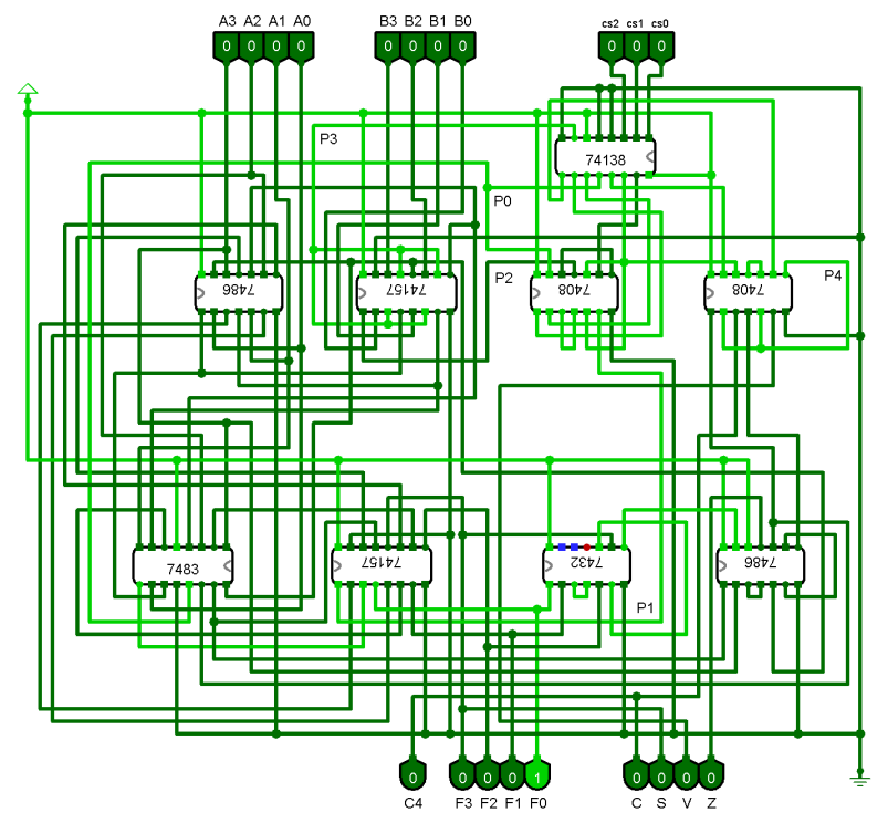
This project involves the design and simulation of a 4-bit Arithmetic Logic Unit (ALU) as part of the coursework for CSE 306 - Computer Architecture Sessional. The ALU performs arithmetic and logic operations directed by control signals. It also implements a status register to indicate flags such as Carry (C), Overflow (V), Sign (S), and Zero (Z).
Problem Specification
The 4-bit ALU is controlled by three selection bits (cs2, cs1, cs0) and supports the following operations:
| Control Signals | Function Description |
|---|---|
000 | Add with carry (A + B + 1) |
001 | XOR (A ⊕ B) |
010 | Transfer A (Output is A) |
011 | Add (A + B) |
100 | Complement A (A’) |
111 | Increment A (A + 1) |
Flag Definitions
- Carry Flag (CF): Indicates carry-out.
- Overflow Flag (VF): Indicates signed addition overflow.
- Sign Flag (SF): Indicates if the result is negative.
- Zero Flag (ZF): Indicates if the result is zero.
Design Overview
The ALU is designed using a combination of control logic, multiplexing, and combinational circuits.
Key Components
- Arithmetic Path: Performs addition, increment, and transfer operations using a 4-bit parallel adder.
- Logic Path: Performs XOR and complement operations.
- Control Logic: Decodes the control signals to direct operations and select paths.
Complete Circuit Diagram

Required ICs
| IC Name | Description | Count |
|---|---|---|
| IC 74138 | 3-to-8 line decoder/demultiplexer | 1 |
| IC 7486 | Quad 2-input XOR gate | 2 |
| IC 74157 | Quad 2-line to 1-line data selector/mux | 2 |
| IC 7408 | Quad 2-input AND gate | 2 |
| IC 7483 | 4-bit binary full adder | 1 |
| IC 7432 | Quad 2-input OR gate | 1 |
Simulation
The design is simulated using:
- Logisim-2.7.1 or Logisim-Ita-2.16.1.4 (cross-compatible).